
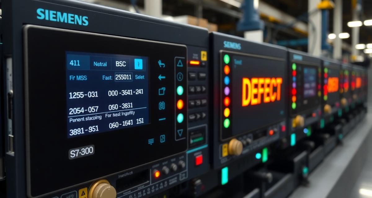
Fewer than 5% of Siemens S7-300 DEFECT states are caused by actual CPU hardware failure. The vast majority — approximately 95% — are caused by one of three software-layer conditions: a corrupted SIMATIC memory card (MMC) that the CPU cannot load during startup, an incompatible firmware update that was interrupted or applied to the wrong CPU type, or a persistent OB missing condition that the CPU cannot resolve after repeated restart attempts. This Siemens S7-300 DEFECT mode recovery guide is designed specifically for scenarios without a STEP 7 programmer available — covering hardware-only procedures executable directly from the CPU front panel as well as online recovery steps for when a programming station can be reached. In all three cases, the all-LEDs-flashing DEFECT pattern is the CPU’s way of reporting that it completed its startup self-test successfully but failed to reach the point where it can execute user program — a situation that is recoverable without replacing the CPU hardware. This guide covers the complete Siemens S7-300 DEFECT mode recovery without STEP 7 programmer procedure from MMC removal test through complete memory reset.
- The DEFECT LED Pattern: What Each LED Combination Means
- DEFECT Recovery Behavior by S7-300 CPU Model
- Recovery Without a STEP 7 Programmer — Field Recovery Options
- Step 1: Remove the MMC and Attempt a Cold Restart
- Step 2: Perform a Complete CPU Memory Reset (MRES)
- How to Perform MRES Using the Mode Selector Switch
- Step 3: Reload the User Program from a Backup MMC or STEP 7 Online
- Step 4: Firmware Corruption Recovery — When MRES Does Not Resolve DEFECT
- Step 5: CPU Hardware Failure Diagnosis
- Technical Validation
- Frequently Asked Questions
The DEFECT LED Pattern: What Each LED Combination Means
The DEFECT pattern on an S7-300 CPU is specifically characterized by alternating or simultaneous flashing of the RUN (green) and STOP (red) LEDs. The exact pattern varies by CPU model and DEFECT type:
| LED Pattern | Meaning |
|---|---|
| RUN flashing green + STOP flashing red simultaneously | Classic DEFECT mode: startup sequence failed; hardware test passed |
| All LEDs flashing alternately | DEFECT mode with hardware test failure indication |
| STOP flashing slowly (2 Hz) only | Memory reset required (not a DEFECT — a normal state) |
| STOP solid + SF solid | Non-DEFECT fault (programming error or module fault) |
Critical distinction: DEFECT mode (RUN + STOP both flashing) is NOT the same as STOP mode (only STOP LED solid red). A CPU in STOP can be restarted normally. A CPU in DEFECT requires active recovery action.
When the DEFECT pattern appears immediately after: – A memory card was inserted or replaced → MMC content is the likely cause – A firmware update was performed → firmware corruption – A power cycle with no hardware changes → MMC content corruption from improper power-down during a write cycle
DEFECT Recovery Behavior by S7-300 CPU Model
Not all S7-300 CPUs support the same DEFECT recovery methods. Before starting the recovery procedure, identify the CPU model from the faceplate label — the recovery path differs by model:
| CPU Model | MMC Firmware Recovery | DP Interface | DEFECT Recovery Notes |
|---|---|---|---|
| CPU 312 / CPU 313 (early HW rev.) | Not supported | None | Firmware corruption requires factory repair; MRES + program reload is the only field option |
| CPU 314 (HW rev. 01 and earlier) | Not supported | None | Same as CPU 312/313 — firmware corruption = factory repair |
| CPU 314 (HW rev. 02 and later) | Yes — via MMC firmware file | None | MMC-based firmware update supported from specific HW revision; check HW rev. on faceplate label |
| CPU 315-2DP | Yes | 1× PROFIBUS DP | DEFECT can result from corrupted DP master configuration on MMC — download full hardware config after MRES |
| CPU 317-2DP / CPU 317-2PN/DP | Yes | 2× interfaces | Larger program memory requires MMC ≥ 2 MB for firmware recovery files; firmware file is CPU-model-specific |
CPU 315-2DP and CPU 317 specific consideration: these CPUs store the PROFIBUS DP master configuration as a separate data block on the SIMATIC MMC. If this block is corrupted (incomplete write during a power interruption), the CPU can enter DEFECT mode even when the user program blocks are intact. The recovery procedure is identical — MRES + re-download of the complete STEP 7 project, which includes the hardware configuration with the DP master settings. After recovery, verify the PROFIBUS DP slaves reconnect by checking HW Config online.
Identifying the hardware revision: the CPU hardware revision (HW:) is printed on the CPU faceplate label, below the order number. For CPU 314, the key revision boundary for MMC firmware support is HW 02 — revisions 01 and below do not support field firmware recovery.
For CPU model comparison in the context of OB80 cycle time behavior differences between CPU 312, 314, 315, and 317, see Siemens S7 300 Ob80 Cycle Time Exceeded Fix.
Recovery Without a STEP 7 Programmer — Field Recovery Options
When the Siemens S7-300 enters DEFECT mode and no STEP 7 / TIA Portal programming station is reachable — either because the PLC is at a remote site, the laptop is unavailable, or the licensed software is not accessible — recovery is still possible using only hardware procedures. These steps do not require a software connection to the CPU.
The following hardware-only recovery actions can be performed without any programming software or MPI/PROFIBUS connection:
- MMC removal test (Step 1 below): identifies and eliminates corrupted memory card content as the DEFECT cause using only power cycling and the mode selector switch
- MRES via mode selector (Step 2): performs a complete CPU memory reset using only the front-panel key switch — no software required
- Reload from backup MMC (Step 3, Option A): if a pre-programmed backup MMC is available on-site, the user program can be restored by inserting the card and setting the mode selector to RUN, with no laptop required
- Firmware update via MMC (Step 4): on supported CPU models, firmware recovery also requires only the mode selector and a prepared MMC — no STEP 7 connection needed
The only recovery steps that require a STEP 7 or TIA Portal programming station are: formatting a corrupted MMC (requires STEP 7 → PLC → Memory Card File → Format) and downloading a user program from a project archive if no backup MMC is available. If neither STEP 7 nor a backup MMC is on-site, the CPU can still be stabilized in a known STOP state (after MRES) until a programming station can be brought to the site.
Step 1: Remove the MMC and Attempt a Cold Restart
The fastest diagnostic step for DEFECT mode: remove the SIMATIC memory card (MMC) and power-cycle the CPU. If the DEFECT state was caused by a corrupted MMC, removing the card allows the CPU to start with its built-in startup behavior (no user program, but no corrupted content either).
MMC location: the SIMATIC MMC (catalog number 6ES7953-8Lx00-0AA0) is a 3.3V MultiMediaCard inserted in the slot on the CPU faceplate, behind a hinged cover. It is NOT a standard Compact Flash or SD card — using non-Siemens memory cards in the MMC slot can corrupt the CPU’s startup behavior.
Procedure: 1. Set the mode selector to STOP position (prevents automatic RUN startup) 2. Power off the CPU (remove the 24VDC supply) 3. Open the hinged cover on the CPU faceplate 4. Remove the MMC card 5. Power on the CPU 6. Observe LEDs: if DEFECT mode clears and CPU reaches STOP (solid red STOP LED only), the MMC content was the cause
If the DEFECT clears without the MMC: the MMC is corrupted. Do not reinsert the corrupted MMC. Format the MMC using STEP 7 (PLC → Memory Card File → Format), then download the user program to the MMC from a backup.
If the DEFECT persists without the MMC: the cause is a CPU hardware or firmware issue — proceed to Step 4.
Step 2: Perform a Complete CPU Memory Reset (MRES)
A CPU memory reset (MRES — Memory Reset) clears the CPU’s internal memory, including any corrupted program blocks, incorrect mode settings, and retain data. It returns the CPU to a factory-default memory state. The user program is NOT deleted from the MMC during MRES — only the CPU’s internal RAM is cleared.
When MRES is needed: when the CPU cannot exit DEFECT mode after MMC removal, when the CPU has a persistent STOP state that cannot be resolved online, or when uploading a new program requires clearing all existing program blocks first.
Important pre-MRES action: back up the current user program if possible. If the CPU is in DEFECT and cannot connect online, the last known-good program backup from STEP 7 or from a good MMC is the recovery source.
How to Perform MRES Using the Mode Selector Switch
The S7-300 CPU mode selector is a 3-position key switch: RUN — STOP — MRES. The MRES position is spring-loaded (it returns to STOP when released).
MRES procedure:
1. Current CPU state: any (DEFECT, STOP, or even RUN — though RUN requires STOP first)
2. Turn key to STOP position → wait for STOP LED to go solid (if not already)
3. Turn key to MRES position → hold for 3 seconds → STOP LED begins flashing
4. Release key back to STOP position → STOP LED goes solid briefly
5. Turn key to MRES position again within 3 seconds → STOP LED flashes rapidly
6. Release key to STOP position → MRES is executing
7. STOP LED shows a brief pattern of flashing, then goes solid red
8. MRES complete — CPU is in STOP with empty internal memory
Confirming MRES completed: in STEP 7, attempt to go online with the CPU. The module information should show “No program loaded.” If the CPU still shows the previous program online, MRES did not complete — repeat the procedure, paying attention to the timing of the key position changes.
Step 3: Reload the User Program from a Backup MMC or STEP 7 Online
After a successful MRES, the CPU has no user program and is in STOP. The user program must be restored:
Option A — Reload from a backup SIMATIC MMC: Insert a known-good MMC (containing the correct program backup). Set mode selector to RUN. The CPU automatically loads the program from the MMC into CPU RAM and starts the user program if all OBs and startup conditions are met.
Option B — Download from STEP 7 online:
STEP 7 → CPU in STOP (after MRES) →
Online → Download to module (CPU)
→ Download all blocks
→ After download complete, set CPU to RUN
After reload, verify the diagnostic buffer (clear from MRES) shows only a normal startup sequence (STARTUP event) with no fault events. If the DEFECT pattern returns after program reload, a specific program block is causing the DEFECT — check for missing OBs and blocks referenced by the user program that do not exist in the downloaded project.
For S7-300 MMC memory card corruption and recovery options, see Siemens S7-300 Mmc Memory Card Corruption Recovery Fix. For the complete SF LED diagnostic sequence that follows a successful DEFECT recovery, see Siemens S7-300 Sf Led Error Diagnosis Step By Step Fix.
Step 4: Firmware Corruption Recovery — When MRES Does Not Resolve DEFECT
If MRES does not resolve the DEFECT mode and the MMC is confirmed good (or removed), the CPU’s internal firmware may be corrupted. This is rare but can occur if a firmware update was interrupted (power loss during the flash write cycle) or if a firmware file intended for a different CPU type was applied.
Firmware recovery options for S7-300:
For CPUs that support firmware update via SIMATIC MMC (most S7-300 CPU3xx series, V3.0 firmware and later): 1. Prepare an MMC with the firmware update file (download from Siemens SIOS: search the exact CPU order number + “firmware update”) 2. Power off the CPU 3. Insert the firmware MMC 4. Power on the CPU → the CPU detects the firmware file on the MMC and automatically initiates the firmware update 5. LEDs flash during update — do NOT interrupt power during this phase 6. CPU restarts with new firmware and enters STOP
Not all S7-300 CPUs support MMC-based firmware recovery. Older CPU3xx models (CPU 313, CPU 314 without firmware update slot) require factory repair for firmware corruption.
Step 5: CPU Hardware Failure Diagnosis
If MRES completes, a known-good program is loaded, and the DEFECT pattern immediately returns, or if the CPU cannot complete MRES, an internal hardware failure exists. Hardware failures that generate DEFECT mode include:
- Failed CPU internal RAM (self-test finds memory errors)
- Corrupt boot ROM (firmware storage failure not recoverable by MMC update)
- Failed backplane bus interface chip
At this point, the CPU requires factory repair or replacement. Before ordering a replacement CPU: 1. Verify the 24VDC power supply voltage is exactly within spec (20.4–28.8V DC) — insufficient supply voltage can cause false DEFECT mode during the CPU’s internal test 2. Verify the power supply ripple is within spec — ripple exceeding 3.6V peak-to-peak can cause CPU initialization failures
If a replacement CPU is required, the backup MMC or STEP 7 project serves as the program source for the replacement unit.
For S7-1200 and S7-1500 error code diagnosis, see: Siemens S7-1200 Error Codes Complete List
Technical Validation
S7-300 DEFECT mode conditions and MRES procedure from the Siemens STEP 7 Error Code Reference Document 770453. S7-300 memory card recovery and program reload after CPU memory reset from Industrial Monitor Direct Siemens S7-300 MMC card recovery guide. Industrial PLC recovery training from NIC.edu PLC certification programs.
Frequently Asked Questions
Does performing an MRES delete the user program from the SIMATIC MMC?
No. MRES clears only the CPU’s internal RAM — the SIMATIC MMC (if inserted) retains its content unchanged. After MRES, when the CPU is set to RUN, it automatically loads the program from the MMC back into CPU RAM (if an MMC is inserted). If you want to clear both the CPU RAM and the MMC content, format the MMC separately in STEP 7 (PLC → Memory Card File → Format) before or after the MRES. Formatting the MMC requires a separate step and removes ALL files from the MMC including the user program.
After MRES and program reload, the S7-300 CPU reaches RUN for 2 seconds then goes to STOP with the SF LED. Is this still related to the original DEFECT?
No — this is a new, different condition. The original DEFECT was cleared by MRES. The new STOP after a brief RUN indicates that the loaded program has a fault condition (a missing OB that is called during startup, an I/O module fault that the program cannot handle because OB82 is missing, or a cycle time exceeded). Check the diagnostic buffer for the new fault entry generated during the 2-second RUN period. The diagnostic buffer is cleared by MRES, so any entries present after MRES + restart are new events from the current run attempt.
Can STEP 7 connect online to an S7-300 CPU that is in DEFECT mode to read the diagnostic buffer?
Sometimes. Whether STEP 7 can connect depends on whether the CPU’s TCP/IP stack (for CP module-based connections) or MPI/PROFIBUS interface is initialized before the DEFECT condition is detected. If the CPU reaches a point in startup where the communication interface is active but the user program loading fails (the most common DEFECT scenario with MMC corruption), STEP 7 can connect and read the diagnostic buffer. If the DEFECT occurs during the hardware self-test phase (before communication interfaces are initialized), STEP 7 cannot connect. In the latter case, the mode selector switch and physical LED pattern are the only diagnostic tools available.