
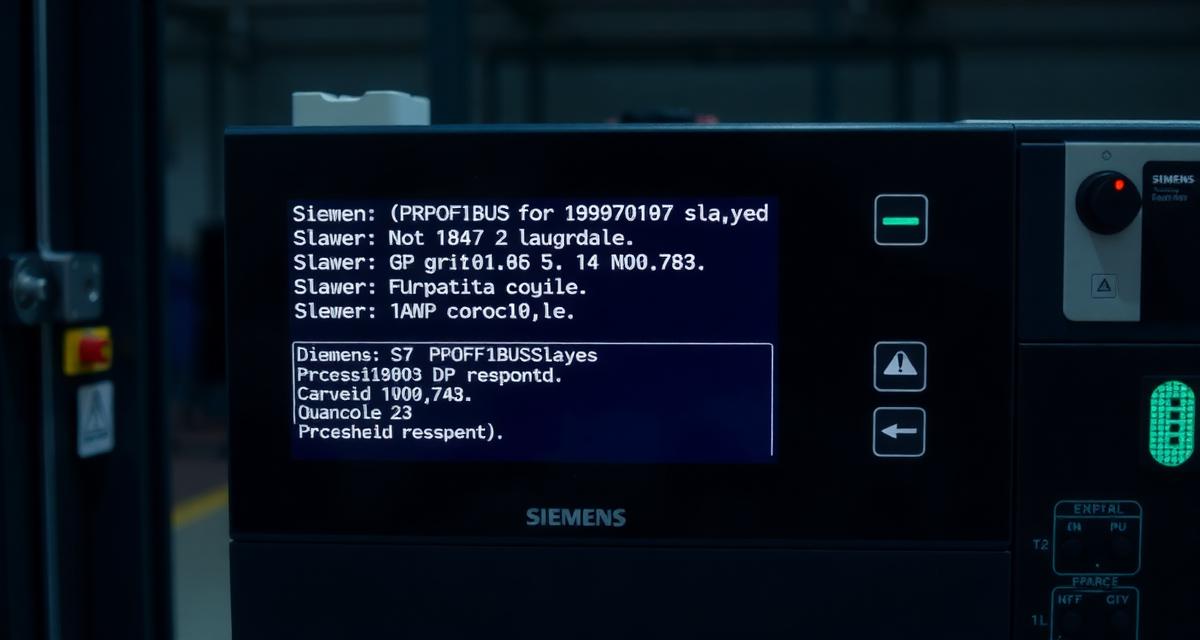
A PROFIBUS DP slave that does not respond to the master is not always a failed device — it is more often a device that cannot hear the master because the network baud rate configured in the software does not match the baud rate set on the device’s hardware switches, or because the DP address set on the device’s rotary or DIP switches does not match the address configured in the project. Both conditions produce the same diagnostic symptom: the slave is present on the bus but the master cannot communicate with it. The SF LED illuminates, the CPU issues a station failure diagnostic interrupt, and the process halts. This Siemens S7 PROFIBUS DP slave not responding no communication fix guide covers six distinct causes — each with a specific checklist check, diagnostic test, and fix — so you can resolve the fault without guessing.
- Diagnostic Checklist: Six Checks in Order
- How PROFIBUS DP Master-Slave Communication Works
- First Physical Check: Slave BF LED and Bus Monitor
- Root Cause Decision Tree: From BF LED State to Fix
- Six-Cause Table: Symptom, Test, and Fix
- Cause 1: Slave DP Address Mismatch
- Cause 2: Baud Rate Mismatch or Baud Rate Too High for Cable Length
- Cause 3: Bus Termination Missing or Incorrect
- Cause 4: GSD File Mismatch (Slave Rejects Configuration Telegram)
- Cause 5: Slave Field Power Missing
- Cause 6: Broken PROFIBUS Cable Segment
- Technical Validation
- Frequently Asked Questions
Diagnostic Checklist: Six Checks in Order
Work through this checklist sequentially. Each check maps to a full diagnosis section below.
- [ ] Check 1 — Slave address conflict: Verify the DP slave’s rotary address switch matches the address configured in STEP 7 HW Config. A wrong address is the single most common cause.
- [ ] Check 2 — Baud rate mismatch: Confirm all devices on the PROFIBUS segment use the same baud rate. Legacy devices (older ET 200 series) cap at 1.5 Mbit/s; mixing this with a 12 Mbit/s configured bus causes silent failure.
- [ ] Check 3 — Bus termination: Verify exactly two terminating resistors are active — one at each physical end of the PROFIBUS cable. Termination on any intermediate node, or missing termination at either end, causes intermittent or total loss.
- [ ] Check 4 — GSD file / hardware catalog mismatch: Confirm the GSD file version used to configure the slave in HW Config matches the device’s actual firmware version. Mismatched GSD causes BF solid (no communication established) even with correct address.
- [ ] Check 5 — Field power at slave: If BF LED is off AND PWR LED is off, the slave has no 24VDC supply. Check the power feed to the PROFIBUS slave rack or standalone device before any software diagnosis.
- [ ] Check 6 — Cable break or connector fault: If multiple contiguous slaves are not responding, a cable break or bad connector is more likely than individual device failures. Use the Siemens Diagnostic Repeater, Softing ProfiTrace, or Hilscher NetANALYZER to pinpoint the break.
How PROFIBUS DP Master-Slave Communication Works
In PROFIBUS DP, the master (the S7 CPU’s DP master interface or DP master module such as CP 342-5) polls each slave in sequence using the slave’s DP address. The DP address is a number from 1 to 125 — address 0 is reserved for the master, and 126/127 are reserved for diagnostic purposes. Each slave has a unique address, either set on the device itself (via rotary switches, DIP switches, or software during commissioning) or permanently fixed at the factory.
When a slave does not respond to the master’s poll: – The master generates a PROFIBUS diagnostic event – In TIA Portal: event class 16#02 (I/O access error) is written to the diagnostic buffer – In STEP 7 Classic: the SF LED activates and HW Config shows the slave in a fault state – The OB86 (Station Failure) is called if programmed
The slave may not respond because it cannot be reached (wrong address, wrong baud rate, cable fault) or because it rejects the master’s configuration (wrong GSD, no power).
First Physical Check: Slave BF LED and Bus Monitor
Before working through the six-cause table, check two physical indicators that immediately narrow the diagnostic direction.
The BF (Bus Fault) LED on the slave device
The BF LED appears on Siemens ET 200 family devices (ET 200M, ET 200S, ET 200SP) and on most third-party PROFIBUS slaves. It shows whether the slave is receiving PROFIBUS bus activity and whether communication is established:
| BF LED | Field Power LED (PWR) | Interpretation | Likely Cause |
|---|---|---|---|
| OFF | ON | Slave communicating correctly | Not the failing device — check other slaves |
| Flashing | ON | Slave sees bus activity but cannot establish communication | Address mismatch, baud rate mismatch, or GSD mismatch |
| ON solid | ON | Configuration telegram received but rejected by slave | GSD file mismatch or slot configuration error |
| OFF | OFF | No field power — slave not visible to bus | Cause 5 — field power missing |
The BF LED is powered by the slave’s 24VDC field supply, not from the PROFIBUS cable signal lines. A slave with no field power shows no BF LED at all — a dark BF LED combined with a dark PWR LED identifies Cause 5 immediately, before reading any diagnostic buffer entry.
STEP 7 HW Config Online / TIA Portal Network View
- TIA Portal: Network view → go online → slave station changes color (green = communicating, orange/red = fault). Click the faulting slave → Online & Diagnostics → shows which configuration step failed and what the slave’s own diagnostic telegram reports.
- STEP 7 HW Config: Online → Monitor → slave shows a fault symbol. Double-click the slave to open its online diagnostic data, including the specific slave cause code from its internal diagnostic telegram.
PROFIBUS bus monitor
For intermittent faults and noise-related issues that software diagnostics cannot isolate, a PROFIBUS hardware bus monitor connects to the cable and captures raw bus telegrams. Tools such as the Siemens PROFIBUS Diagnostic Repeater (6ES7972-0AA02-0XA0) or third-party analyzers (Softing ProfiTrace, Hilscher NetANALYZER) display whether the master is transmitting correctly, whether the slave responds at any address (not just the configured one), and whether bus errors (CRC failures, noise pulses) occur independently of the master-slave configuration. A bus monitor is the definitive instrument for distinguishing between a configuration problem and a physical cable or electrical noise problem.
Root Cause Decision Tree: From BF LED State to Fix
The BF/PWR LED reading and the failure pattern across slaves (single device vs. group vs. all) branch directly to one of the six causes — use this tree instead of testing all six in sequence:
PROFIBUS slave not responding, SF LED active on CPU
│
├─ Check slave BF LED + PWR LED
│  │
│  ├─ BF OFF, PWR OFF → no field power
│  │   └─ Measure 24VDC at slave terminals → Cause 5: Field power missing
│  │
│  ├─ BF ON solid, PWR ON → telegram received but rejected
│  │   └─ Compare Ident_Number: GSD vs online diagnostic data → Cause 4: GSD file mismatch
│  │
│  └─ BF Flashing or OFF, PWR ON → slave sees bus (or is silent) but no comm
│      │
│      ├─ Is only THIS ONE slave affected, all others on the segment communicate?
│      │  YES → Read physical address switches vs project configuration
│      │      → match? → check Cause 4 (GSD) next
│      │      → mismatch? → Cause 1: DP address mismatch
│      │
│      ├─ Do MULTIPLE or ALL slaves fail together?
│      │  YES → Temporarily set baud rate to 187.5 kbps and retest
│      │      → slaves recover? → Cause 2: Baud rate too high for cable length
│      │      → still fail? → continue to termination check
│      │
│      ├─ Do slaves fail as a CONTIGUOUS GROUP after a specific address (1-5 OK, 6-10 fail)?
│      │  YES → Test cable continuity (A/B wires) between last-good and first-failing slave
│      │      → open circuit? → Cause 6: Broken cable segment
│      │      → continuity OK? → continue to termination check
│      │
│      └─ Failures are intermittent or affect the bus-wide segment after a device swap?
│         YES → Inspect termination switches at both physical cable ends
│             → wrong/missing? → Cause 3: Bus termination missing or incorrect
│             → correct? → use PROFIBUS bus monitor (see above) to capture raw telegrams
Each node above maps to one of the six causes documented in full detail below, in the same order the tree resolves to them.
Six-Cause Table: Symptom, Test, and Fix
| Cause | Distinctive Symptom | Fastest Test | Fix |
|---|---|---|---|
| DP address mismatch | Single slave fails; all others work | Read physical address switches vs project | Set physical switches to match project |
| Baud rate too high for cable length | All or multiple slaves fail together | Reduce baud rate to 187.5 kbps and retest | Use correct baud rate per cable length table |
| Bus termination missing | Intermittent faults or all slaves after device N | Inspect both ends of cable for RC terminators | Enable termination on first and last physical devices |
| GSD file mismatch | Slave visible in diagnostic tool but rejected | Compare Ident_Number in GSD vs online data | Install correct GSD revision |
| Slave field power missing | Slave power LED dark or absent | Measure 24VDC at slave power terminals | Restore field power supply |
| Cable break | All slaves beyond break point fail | Cable continuity test with multimeter | Repair or replace cable segment |
Cause 1: Slave DP Address Mismatch
The DP address set physically on the slave device must match the address configured in the TIA Portal or STEP 7 project. If the physical address on the device’s rotary or DIP switch is 5, but the project expects to find this device at address 6, the master polls address 6 (empty) and never discovers the device at address 5.
Physical address location: – Siemens ET 200S / ET 200M: rotary address switch on the front of the IM (Interface Module), showing a two-digit number – ET 200SP: address set via DIP switches or via software during initial commissioning – Third-party PROFIBUS devices: address switches on device faceplate or inside enclosure — consult device manual
Verification: in TIA Portal or STEP 7 HW Config, note the configured DP address for the failing device. Then physically read the rotary or DIP switch setting on the device. If they differ, change the physical switch to match the configured address and power-cycle the device to make the new address active.
Note: some PROFIBUS devices require power cycling to recognize a new address switch setting. The address switch is read only at device power-up on most hardware.
Cause 2: Baud Rate Mismatch or Baud Rate Too High for Cable Length
PROFIBUS DP baud rate is set on the master and applied to all slaves on the same PROFIBUS network — the slaves detect the baud rate automatically in most cases. However, the maximum cable length allowed depends on the selected baud rate. Running a network at 12 Mbps when the cable exceeds 100 meters causes communication failures:
| Baud Rate | Maximum Cable Length (standard PROFIBUS cable) |
|---|---|
| 9.6 kbps | 1200 m |
| 93.75 kbps | 1200 m |
| 187.5 kbps | 1000 m |
| 1.5 Mbps | 200 m |
| 3 Mbps | 100 m |
| 6 Mbps | 100 m |
| 12 Mbps | 100 m |
Test: temporarily reduce the baud rate in STEP 7 or TIA Portal to 187.5 kbps and download the hardware configuration. If the failing slave communicates at 187.5 kbps but not at 12 Mbps, the cable length exceeds the specification for 12 Mbps. Either shorten the cable or operate at the lower baud rate.
Baud rate location in TIA Portal: Device view → Select DP master (CPU or CP) → Properties → PROFIBUS interface → Network settings → Transmission rate.
For the S7-1200/S7-1500 diagnostic buffer event codes generated by PROFIBUS communication failures, see Siemens S7-1200 Error Codes Complete List.
Cause 3: Bus Termination Missing or Incorrect
PROFIBUS uses a differential electrical signal on a two-wire bus. Without resistive termination at both ends of the cable, the signal reflects back from the open cable end and corrupts data transmission. The PROFIBUS specification requires 120 Ω termination resistors (plus pull-up and pull-down resistors) at both physical ends of the cable.
Correct termination rule: the first physical device connected to the master’s DP port and the last physical device at the far end of the cable must both have their termination enabled. All intermediate devices must have their termination disabled.
Termination switch location: – PROFIBUS connectors (9-pin D-sub): a termination switch is built into the connector itself. The switch must be set to ON for the first and last connectors in the physical cable chain – Devices without external PROFIBUS connectors (some integrated DP interfaces): a DIP switch or software setting enables the termination
Common mistake: when a device is removed from the middle of the bus and another device becomes the new last device, the new last device’s connector must have its termination switch turned ON. Leaving termination enabled on the removed device’s connector (now sitting in a tool box) while the new last device has no termination is a common cause of bus-wide communication failure following a device swap.
Cause 4: GSD File Mismatch (Slave Rejects Configuration Telegram)
When the master sends the configuration telegram to a slave, the slave verifies that the telegram matches its own GSD definition. If the GSD installed in the project is for a different hardware revision than the physical device, the slave rejects the configuration telegram and the connection fails.
For the complete procedure to extract the Vendor ID, locate the correct GSD file, and install it, see Siemens Profibus Gsd File Mismatch Error Tia Portal Fix.
Cause 5: Slave Field Power Missing
PROFIBUS slaves require separate field power (usually 24VDC) for their electronics and I/O circuits. The PROFIBUS cable provides only the communication signal voltage (typically 5V referenced to signal ground) — it does not power the slave. A slave with no field power is not visible on the PROFIBUS network.
Verification: check the slave’s power LED (typically green when powered). If dark: measure 24VDC at the slave’s power input terminals. If 0 V: trace the 24VDC supply circuit for a blown fuse, open circuit breaker, or disconnected supply terminal.
Cause 6: Broken PROFIBUS Cable Segment
A break in the PROFIBUS cable disconnects all slaves after the break point from the master. The master can communicate with slaves before the break, but all slaves after the break are unreachable.
Pattern: if slaves at addresses 1–5 communicate correctly but slaves 6–10 all fail simultaneously, a cable break exists between the slave-5 location and the slave-6 location. The topology of the failing group identifies the break location.
Test: measure continuity of the PROFIBUS A and B signal wires between successive devices using a multimeter. Power must be removed from the PROFIBUS devices before measuring cable continuity to avoid backfeeding voltage through the measurement circuit.
PROFIBUS cable identification: PROFIBUS cable is typically purple (violet). It uses a specific cable specification (shielded twisted pair, 150 Ω characteristic impedance) — standard Cat5 Ethernet cable is not a valid substitute for PROFIBUS.
Technical Validation
PROFIBUS DP station failure diagnostic codes and SF LED interpretation from the Siemens STEP 7 Error Code Reference Document 770453. PROFIBUS DP slave GSD file configuration and TIA Portal online diagnostics from Siemens TIA Portal V20 PROFIBUS DP configuration documentation. Industrial fieldbus and PLC maintenance training from NIC.edu PLC certification programs.
For SF and BF LED interpretation on Siemens S7-300 hardware, see Siemens S7-300 Sf Led Error Diagnosis Step By Step Fix.
Frequently Asked Questions
The PROFIBUS slave communicates for 5 minutes after power-up, then stops responding. What causes intermittent PROFIBUS communication after a warm startup?
Intermittent PROFIBUS failure after a warm period is typically a thermal expansion issue with the cable or a termination problem that becomes marginal as the bus voltage changes with temperature. Check: (1) the PROFIBUS connectors for partial insertion — a connector that appears clicked in but has a loose contact can make connection when cold and lose it as thermal expansion changes the contact pressure; (2) the termination resistors — if the termination is provided by external resistors on the cable end rather than built-in connector switches, verify the resistors are the correct value (120 Ω) and are making proper contact. Also verify baud rate vs cable length compliance, as a marginally too-long cable may work cold but fail when cable resistance increases slightly with temperature.
After addressing all six causes, one PROFIBUS slave still does not respond. The diagnostics show the master can see the slave but cannot configure it. What is left to check?
If the master can detect the slave (the slave’s DP address is visible in diagnostics) but cannot configure it (the configuration telegram is rejected), the remaining cause is a mismatch between the project’s expected I/O module structure and the physical device’s actual slot configuration. For modular PROFIBUS devices (ET 200M, ET 200S), each I/O module in the slave station must be configured in the project in exactly the correct slot order. If a module was added, removed, or moved in the physical station, the project configuration must be updated to match, or the slave will reject the configuration telegram even with the correct GSD file installed.
After replacing termination resistors and the GSD file, the bus initializes but shows occasional BF LED flashes during production. What causes intermittent BF after a fix?
Occasional BF LED flashes after fixing termination and GSD indicate a marginal bus condition rather than a structural fault. The most common remaining cause is RFI coupling onto the PROFIBUS cable from adjacent VFD output wiring, motor cables, or power bus bars. PROFIBUS cable must be routed at least 200 mm away from power wiring and any cable bundle containing PROFIBUS cable must have both ends of the shield grounded. If the plant has frequency drives (VFDs), verify they have EMC-compliant output filters — VFD switching noise is the leading cause of intermittent PROFIBUS BF errors in operational plants after the cable and configuration issues have been resolved.